Decoding the Thermal Incinerator Diagram
For process engineers, a thermal incinerator diagram (or P&ID) is the roadmap to compliance. It reveals how a system safely converts hazardous Volatile Organic Compounds (VOCs) into harmless CO2 and water vapor.
At ABOUT US, we design these systems daily. Below, we explain the critical sections you will find in any standard thermal oxidizer schematic.
1. The Core Components (What the Diagram Shows)
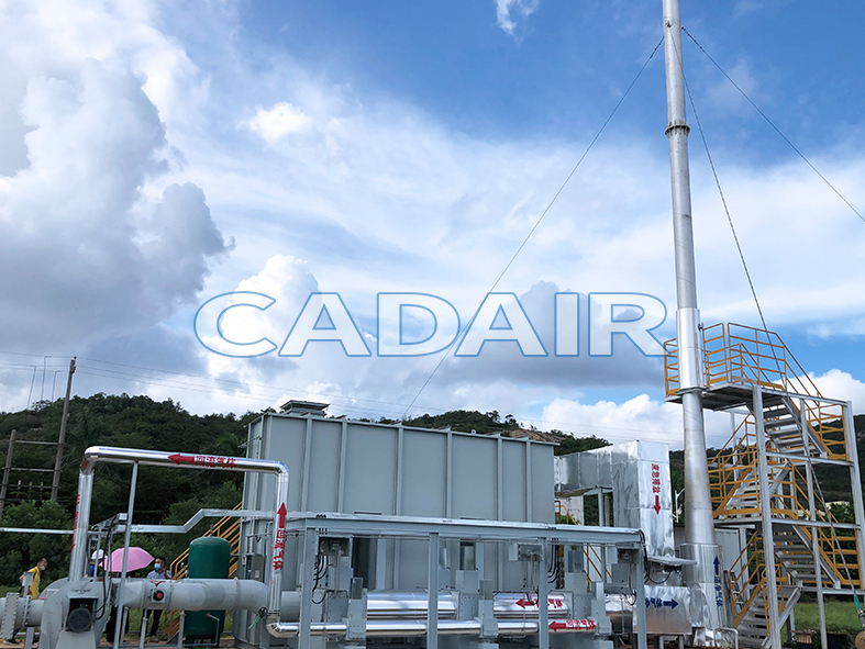
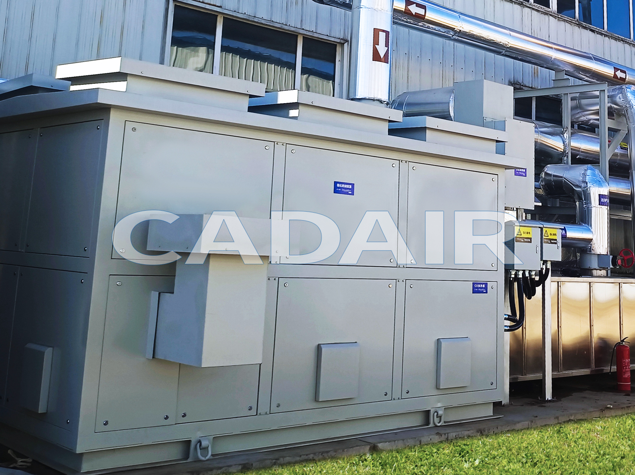
A standard Direct Fired Thermal Oxidizer (TO) diagram typically features three main sections:
- The Burner Assembly: Usually located at the inlet. The diagram will show the fuel train (natural gas line) and the combustion air blower connecting here. This is where the “3Ts” (Temperature, Turbulence) begin.
- The Combustion Chamber (Dwell Chamber): This is the largest section. In a thermal incinerator diagram, this is often depicted as a long, refractory-lined cylinder. The key parameter here is Residence Time (typically 0.5 – 1.0 seconds), ensuring complete destruction.
- The Exhaust Stack: The final vertical outlet. Diagrams often show testing ports here for EPA compliance monitoring.
2. Advanced Diagrams: RTO vs. TO
Not all incinerators look the same. If you are looking at a Regenerative Thermal Oxidizer (RTO) diagram, you will notice distinct differences:
- Ceramic Media Beds: Instead of a simple chamber, an RTO diagram shows vertical towers filled with heat exchange media.
- Flow Switching Valves: You will see a complex valve manifold at the bottom. These valves direct airflow into different towers to recover heat, distinguishing an RTO from a standard TO.
3. Safety Controls in the Diagram
A professional thermal incinerator diagram always includes the safety loop (BMS – Burner Management System):
- LEL Monitors: Sensors shown on the inlet duct to prevent explosion risks.
- Temperature Transmitters (TE): Located in the combustion chamber to modulate the burner firing rate.
- Pressure Switches: To ensure proper draft and fan operation.
Conclusion: Need a Custom P&ID?
A generic thermal incinerator diagram is good for learning, but your facility needs a specific design. Cadair engineers can generate a custom 3D model and Process & Instrumentation Diagram for your unique waste stream.
Request Your System Drawings Contact us to discuss your project requirements.