Sources of VOCs Emissions in Oil & Gas Operations
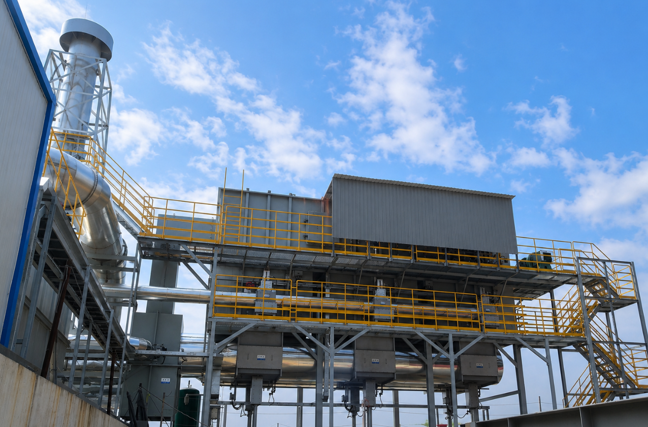
VOCs emissions in oil and gas field scenarios primarily originate from upstream and midstream processes: extraction, gathering, transportation, storage, and on-site wastewater treatment. Pollutants are released both as organized stack discharges and fugitive leaks across facility boundaries.
Hydrocarbons make up the core pollutant profile, and many production sites also generate acidic gaseous impurities such as hydrogen sulfide as co-contaminants.
3. End-of-Pipe Process Selection for Oil & Gas Waste Gas
Treatment systems for oil and gas emissions are custom-engineered based on core parameters: pollutant composition, air volume, and inlet concentration. Below are the mainstream process configurations for typical field scenarios:
| Emission Characteristics | Recommended Process Route | Core Equipment Configuration |
|---|---|---|
| High concentration, with sulfide impurities | Pretreatment + Regenerative Thermal Oxidizer (RTO) | Alkaline scrubber (removes acidic gases such as hydrogen sulfide) + Three-chamber RTO |
| Medium-to-low concentration, dominated by hydrocarbons | Scrubber + Adsorption + Catalytic Oxidation (CO) | Wet scrubber (pre-treats dust and partially soluble contaminants) + Activated carbon / zeolite adsorption unit + Catalytic oxidation system |
4. Industry Technical Standards & Safety Specifications
4.1 Technical Selection Reference
The Practical Manual for VOCs Pollution Control (2nd Edition) — an authoritative technical guide published by China’s Ministry of Ecology and Environment — outlines formal VOCs control requirements for the petroleum refining industry, which serves as the baseline reference for technology selection in oil and gas applications.
- End-of-pipe treatment pathways: Recovery technologies (Category A) including absorption, adsorption, condensation, and membrane separation are recommended as first options. Combined processes that pair recovery technologies with destruction technologies — such as regenerative thermal oxidation (RTO) and catalytic oxidation (CO) — are also fully compliant.
4.2 Safety Requirements for RTO Systems
The Safety Technical Requirements for Regenerative Thermal Oxidizer Systems, a China industry association standard, sets mandatory provisions for safe RTO operation, consistent with global industrial safety best practices:
- The concentration of combustible components in inlet exhaust must be kept below 25% of the Lower Explosive Limit (LEL). High-concentration waste gas must undergo dilution or pre-treatment before entering the oxidation chamber.
- Flame arresters or fire dampers must be installed between upstream process equipment and the RTO unit to block flashback risks.
5. Typical Project Case Studies
Case 1: Organic Waste Gas Treatment for Sewage Pond, Jidong Oilfield (China)
- Pollutant components: Methane, non-methane total hydrocarbons (NMHC), hydrogen sulfide
- Treatment capacity: 8,000 m³/h
- Applied process: Wet scrubber + adsorption unit + CO catalytic oxidation
- Sector: Onshore oil & gas production
Case 2: Waste Gas Treatment for Refinery Wastewater Treatment Plant
- Pollutant components: Benzene, toluene, xylene, non-methane total hydrocarbons (NMHC)
- Treatment capacity: 4,000 Nm³/h
- Inlet concentration: 15,000 mg/m³
- Applied process: Alkaline scrubber + three-chamber RTO
- Compliance standard: Emission Standard of Pollutants for Petroleum Refining Industry (GB 31570-2015) Note: GB 31570-2015 is a mandatory national environmental standard of China issued by the Ministry of Ecology and Environment. It sets legally binding emission limits for air and water pollutants from petroleum refining facilities, and functions as the core compliance benchmark for China’s petrochemical sector — equivalent to the U.S. EPA NESHAP standards or EU Industrial Emissions Directive (IED) for refineries.
- Treatment performance: Outlet VOCs concentration is stably controlled below 40 mg/m³, fully meeting regulatory discharge requirements.